

 Italiano
 Français
 Deutsch
 Español
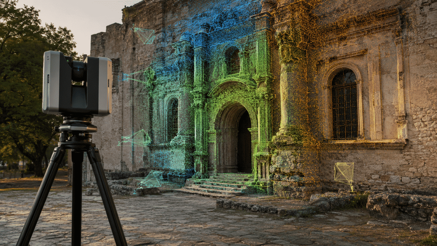
Terrestrial laser scanning and photogrammetry provide different but highly complementary information. A laser scanner can supply a precise, stable 3D framework, while photographs provide the high-resolution color and visual detail needed for textured models, documentation, and orthomosaics. In Agisoft Metashape Professional 2.3.x, these data sources can be brought together in a single project—even when the photographs do not contain GPS coordinates.
This guide explains how to align structured E57 terrestrial laser scans and photos in Agisoft Metashape, use the laser data as the spatial reference for the image block, build a mesh from the scans, and create a planar orthomosaic of a vertical surface. It also clarifies the requirements of the workflow, the role of structured scan data, how to handle multiple scans, and why a generic SLAM or LiDAR point cloud does not necessarily behave in the same way.
Software requirement: this workflow requires Agisoft Metashape Professional Edition. Agisoft officially introduced 3D matching between images and laser scans in Metashape 2.3. For current projects, use the latest available 2.3.x release rather than an older build.
What this combined workflow achieves
The objective is not simply to display photographs and a point cloud in the same chunk. The goal is to calculate a coherent alignment in which:
- the terrestrial scans retain their known position and orientation;
- the photographs align with one another through normal photogrammetric matching;
- the image block also aligns with the structured laser scans;
- previously unreferenced photographs acquire estimated coordinates and orientation angles;
- the scan geometry can be used to build a mesh, while the photographs provide image detail for texturing or orthorectification.
In practical terms, the laser scans act as the stable geometric framework for the project. The photographs are no longer an isolated photogrammetric block: after alignment, their estimated exterior orientation is expressed in the same spatial system as the scans.
Typical project configuration
This workflow is suitable for facades, interiors, industrial structures, archaeological remains, and other objects documented with both static terrestrial scanning and close-range photography. A typical project contains one or more registered scanner stations saved as structured E57 files, together with overlapping photographs of the same visible surfaces.
The photographs may come from a handheld, pole-mounted, or tripod-mounted camera and do not need to include GPS metadata. Their positions and orientations are calculated during alignment. The laser scans provide the spatial framework, while the photographs contribute image detail for texturing and orthorectified products.
Essential requirements before starting
1. Use structured terrestrial laser scans
A structured scan preserves more than XYZ point coordinates. It retains the relationship between measured points and the scanner position from which they were captured. Depending on the source data, it may also provide row and column information, intensity, color, embedded panoramas, and depth information.
That scanner-origin relationship is fundamental to this workflow. Metashape can treat each terrestrial scan position in a camera-like way and use its depth information during matching. A flattened or merged point cloud containing only XYZ or XYZRGB values may have lost the structure required for the same automatic image-to-scan registration.
2. Verify the coordinate reference system
If the scans are already georeferenced, select the correct coordinate system during import. A wrong CRS, an incorrect unit, or a confusion between projected and geographic coordinates can move the data by a large distance or introduce a scale problem.
Absolute coordinates are strongly recommended when the scans must georeference the entire project. A local coordinate system can also be used, but the result will remain local until it is transformed with control information such as surveyed markers.
3. Register multiple scans before the combined workflow
When the project contains more than one scanner station, the scans should ideally already be accurately registered to one another. The strongest approach is normally to complete registration in the scanner manufacturer’s software, verify the residuals and overlap, and then export the individual registered stations as structured E57 files.
Metashape also includes Workflow > Align Laser Scans, so unregistered scans can be aligned inside the application. Nevertheless, entering the combined workflow with the best available laser registration reduces uncertainty and makes troubleshooting easier.
4. Preserve sufficient photographic coverage
The scans provide geometry, but the photographs still need enough sharp detail and overlap to form a reliable image block and to cover the surfaces required in the final product. Avoid blurred images, strong exposure changes, reflective surfaces, and large areas with no visible texture.
Step 1: Import the E57 files as laser scans
- Create or open a Metashape project and work in a single chunk.
- Select File > Import > Import Point Cloud.
- Select one or more structured E57 files.
- Choose the correct coordinate system.
- Enable Use as laser scans.
- For a structured terrestrial scan, use the scanner origin information. If the import dialog offers the Scanner position field, choose the appropriate option for the data—normally Origin for a structured static scan.
- Import the useful attributes, such as color and intensity. If the E57 contains panoramas, the Load images option can import them; otherwise Metashape may generate panoramas from the scan information.
After import, the laser scans appear as dedicated scan assets in the Workspace pane and as point clouds in Model view. Enable Show Laser Scan Positions to verify the scanner stations. Their visible positions are a quick confirmation that Metashape has recognized the scan structure rather than treating the data as an ordinary unstructured cloud.
Opening a scan image from the Photos pane displays the panoramic/depth representation associated with that station. This is one of the elements Metashape uses to connect the laser geometry with the photographic dataset.
Important: if you want accurately georeferenced scans to remain fixed, keep Lock Transform enabled for the scans or their fixed group. If you disable it, Metashape is allowed to modify their external orientation during alignment.
Step 2: Add the photographs to the same chunk
Select Workflow > Add Photos and load all photographs covering the scanned object. Do not create a second chunk for the images: the scans and photographs must be present in the same chunk for the combined alignment.
When the photographs contain no GPS information, the Source view in the Reference pane has no camera coordinates to use. This is not a problem when structured, referenced laser scans provide the spatial framework.
If your photographs do contain approximate GPS positions but you do not want those positions to influence the result, disable their coordinate checkboxes in the Reference pane before alignment. This prevents low-accuracy camera coordinates from competing with a stronger laser-scan reference.
Step 3: Align the photographs with the scans
With the structured scans already imported and correctly positioned, run Workflow > Align Photos. You do not need to run Align Laser Scans again if the scan stations are already registered and fixed.
For photographs without coordinate metadata, Generic preselection is appropriate because candidate image pairs are selected from image content. Reference preselection should not be used when there are no reliable camera coordinates on which to base the selection.
During alignment, Metashape detects features in the photographs, creates matches between overlapping images, estimates camera calibration and exterior orientation, and connects the image block with the structured scan data. When successful, camera icons should appear in the correct locations and orientations relative to the laser cloud.
What changes in the Reference pane?
The distinction between Source and Estimated is essential:
- Source: contains coordinates or angles supplied with the original images. It remains empty when the photos have no GPS/INS metadata.
- Estimated: contains camera positions and orientation angles calculated by Metashape after alignment.
Because the aligned cameras now share the reference frame of the scans, their estimated coordinates can be exported for use in another application if required. Treat these as calculated results, however—not as independently measured GNSS observations.
Step 4: Check the alignment before producing deliverables
Metashape displays the photogrammetric tie point cloud and the laser scans as separate assets. Toggle their visibility independently and inspect the relationship between them. The image-derived tie points should follow the same surfaces as the laser data, without a systematic translation, rotation, scale discrepancy, or local separation.
Also review:
- unaligned or incorrectly oriented cameras;
- areas where photographic tie points float in front of or behind the scan surface;
- incorrect scanner positions;
- coordinate-system and unit mismatches;
- weak image overlap or repetitive texture;
- scan registration errors between different stations.
If the image block itself is unstable, consult our Metashape troubleshooting guide before building the final model.
Step 5: Build a mesh from the laser data
Once alignment is verified, select Workflow > Build Model. Metashape Professional can reconstruct the surface from different source combinations, including:
- Laser Scans: builds the mesh from the laser data only;
- Laser Scans + Depth Maps: combines terrestrial scan data and image-derived depth maps;
- Depth Maps: uses the photographs without laser-scan geometry.
For a facade workflow, selecting Laser Scans produces a mesh whose geometry comes exclusively from the scanner measurements. The aligned photographs can then be projected onto that geometry for texturing or orthomosaic creation.
Trim unwanted parts of the mesh before producing the final raster. Removing irrelevant geometry reduces the processing area and helps prevent unwanted projections onto surfaces outside the facade.
Step 6: Create a planar orthomosaic or facade photoplan
A conventional geographic orthomosaic is projected onto a horizontal mapping plane. A wall or facade instead requires a planar projection oriented parallel to the surface.
One practical method is to place three markers on the mesh:
- Place the first marker at the desired origin of the local 2D plane.
- Place the second marker along the horizontal direction to define the X axis.
- Place the third marker along the vertical direction to define the second axis of the plane.
Then select Workflow > Build Orthomosaic and configure:
- Surface: Model;
- Projection type: Planar;
- Projection plane: Markers;
- Horizontal axis: the vector from marker 1 to marker 2;
- Vertical axis: the vector from marker 1 to marker 3;
- Color source: Images.
The resulting photoplan combines laser-derived geometry with the visual resolution of the aligned photographs. Set the output pixel size according to the camera distance, image resolution, lens, surface detail, and intended scale of use. Selecting a pixel size smaller than the effective image resolution increases the file dimensions without creating additional real detail.
Options such as seamline refinement, hole filling, ghosting filtering, or back-face culling should be selected according to the scene and inspected result. More processing is not automatically better: always compare the generated orthomosaic with the source images and the laser geometry.
Can the laser scans compensate for lower photo overlap?
Structured laser data can make a combined project more tolerant of a less redundant photographic set because the scanner supplies an independent geometric framework. This advantage is most relevant when the photographs are primarily required for color, texture, or orthomosaic generation rather than for reconstructing the entire surface.
It should not be interpreted as permission to ignore normal photogrammetric acquisition rules. Sufficient overlap remains important for:
- reliable feature matching between photographs;
- complete photographic coverage of the object;
- stable camera calibration;
- consistent texture and orthomosaic quality;
- redundancy when some images are blurred, obstructed, or poorly exposed.
If the final geometry comes from the laser scanner and the images are used mainly for color, texture, or a facade photoplan, it may be possible to remove redundant photographs during post-processing. A safer strategy is to capture full photographic coverage in the field, complete an initial alignment, duplicate the chunk, and test a reduced image set without modifying the original result.
Compare the reduced and complete versions by checking camera alignment, tie-point distribution, surface coverage, seamlines, and visible detail in the final texture or orthomosaic. If the leaner dataset produces gaps, weak camera geometry, or inconsistent color coverage, restore the additional photographs.
One scan versus multiple scans
A single structured scan can support the workflow if it covers the required surfaces and provides enough common content for image matching. Georeferencing is recommended when an absolute-coordinate result is required.
For multiple stations:
- register the scans accurately before image alignment;
- retain each station as a structured scan rather than merging everything into an unstructured cloud;
- export the registered stations individually as E57 when possible;
- use a fixed group and Lock Transform when their relative and absolute positions must remain unchanged;
- use Align Laser Scans inside Metashape only when additional registration or refinement is actually required.
Does the same method work with SLAM or aerial LiDAR?
Metashape Professional can import both structured terrestrial scans and unstructured point clouds from SLAM or aerial LiDAR systems. However, importing a point cloud is not the same as preserving the acquisition structure needed by this particular workflow.
A generic unstructured LAS, LAZ, or merged E57 cloud may not retain a distinct scanner origin and depth representation for each acquisition station. Without that information, it cannot be assumed to guide the alignment of non-geotagged photographs in the same automatic way as structured static terrestrial scans.
Trajectory-based LiDAR and SLAM datasets have their own import and alignment options. They can still be combined with imagery, but the setup depends on the available trajectory, timestamps, reference information, overlap, and file structure. For that reason, treat the workflow in this guide specifically as a structured terrestrial laser scanning workflow, not as a universal recipe for every LiDAR source.
Common mistakes to avoid
- Importing the E57 as an ordinary point cloud: enable Use as laser scans or convert the imported asset appropriately.
- Losing scan structure during export: do not merge or flatten registered stations if you need their scanner-origin information.
- Choosing the wrong CRS or units: confirm the scan reference before alignment.
- Allowing accurate scans to move: keep Lock Transform enabled when the laser registration must remain the reference.
- Using Reference preselection without reliable camera coordinates: use image-content-based matching instead.
- Reducing overlap too aggressively: scan geometry cannot create missing image content.
- Building deliverables before validation: compare tie points, camera positions, and laser surfaces first.
Final workflow checklist
- Use Agisoft Metashape Professional 2.3.x.
- Prepare structured terrestrial scans, preferably registered and georeferenced.
- Import the files through File > Import > Import Point Cloud.
- Enable Use as laser scans and confirm CRS, scanner position, and attributes.
- Keep accurate scan transforms locked.
- Add the photographs to the same chunk.
- Disable unreliable camera reference data if necessary.
- Run Align Photos, using Generic preselection when photos have no coordinates.
- Inspect estimated camera coordinates and compare tie points with the scan surfaces.
- Build a model from Laser Scans or Laser Scans + Depth Maps.
- For a facade, define a planar projection with markers and build the orthomosaic from the model.
- Validate scale, orientation, coverage, and raster quality before export.
Conclusion
Aligning structured terrestrial laser scans with photographs in Agisoft Metashape creates a practical bridge between survey-grade geometry and high-resolution visual documentation. The most important factor is not simply the E57 extension, but the preservation of scan structure, scanner positions, and a reliable registration.
When those conditions are met, referenced laser scans can provide the spatial framework for photographs with no GPS metadata. The resulting project can support estimated camera orientation, laser-based mesh reconstruction, photorealistic texturing, and accurate planar orthomosaics for facades, walls, archaeological features, industrial assets, and cultural heritage documentation.
To test the workflow before purchasing, download the free trial of Agisoft Metashape Professional. You can also review the Metashape 2.3.2 update overview for the latest changes.
Frequently asked questions
Can Metashape align photographs without GPS to laser scans?
Yes. In Metashape Professional 2.3.x, an image block without GPS coordinates can be aligned with suitably structured terrestrial laser scans. If the scans are georeferenced and their transforms remain locked, they can provide the spatial reference for the estimated camera positions.
Is an E57 file always a structured laser scan?
No. E57 is a container format and can store different kinds of point-cloud information. Verify that the export preserves individual scanner stations, scanner origins, and the structured row/column or depth information required by the workflow.
Should I build the model from laser scans or depth maps?
Choose Laser Scans when scanner geometry should define the mesh. Choose Laser Scans + Depth Maps when you want to combine scan and image-derived geometry. The best choice depends on scan coverage, image quality, surface detail, and the required deliverable.
Can I create an orthomosaic of a vertical wall?
Yes. Build or import a suitable surface, select a Planar projection in Build Orthomosaic, and define the projection plane with markers or another supported orientation method.
Can a SLAM point cloud replace a structured terrestrial scan in this workflow?
Not automatically. SLAM and aerial LiDAR clouds can be imported, but the specific workflow described here relies on preserved scan-position and depth information. Trajectory-based or unstructured datasets require a workflow tailored to their metadata and acquisition method.