

 Italiano
 Français
 Deutsch
 Español
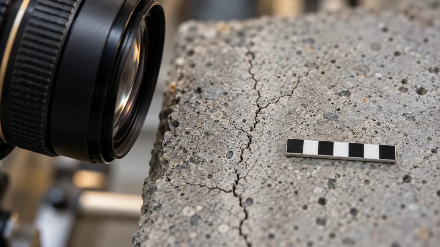
Can Agisoft Metashape measure a crack that is only 10 micrometers wide? The honest answer begins with the source photographs, the optics and a validated measurement procedure. Metashape can locate features in a scaled or referenced image-based model, but a textured 3D reconstruction does not automatically provide a certified minimum or maximum width for a crack below the resolving power of the images.
Pixel footprint is only the first screening test
For a roughly planar, front-facing photograph, estimate the object-space pixel footprint as field of view across the specimen ÷ effective image pixels across that direction. If 100 mm of surface spans 6,000 useful pixels, the footprint is about 0.0167 mm, or 16.7 µm per pixel. A 10 µm opening would occupy less than one pixel in that example, so a defensible width measurement from that photograph is not realistic. With the same 6,000-pixel width across a 1,000 mm specimen, the footprint is about 167 µm per pixel. These are illustrative calculations, not promised accuracy values.
Even several pixels across a crack do not automatically make its width accurate. Optical blur, focus, contrast, surface roughness, illumination, demosaicing and the choice of where each edge starts all matter. NIST’s work on measurements from 2D microscopy images highlights how feature definitions and image-analysis methods can change measured results.
Use two acquisition scales for large specimens
- Overview capture: photograph the full test specimen with overlap and a stable scale or surveyed reference. Use Metashape to establish geometry, orientation, crack location and documentation context.
- Detail capture: photograph each crack region at a controlled working distance with a suitable macro or microscope imaging system. Include a traceable scale in the same plane, avoid perspective changes and retain the unmodified originals.
- Registration: identify where each detail image lies on the overview. Store image IDs, coordinates or reference markers so the measurement remains connected to the specimen.
- Width analysis: define the crack-edge rule, sample profiles perpendicular to the crack and report minimum, maximum and distribution only for segments the method can resolve.
- Validation: compare repeated measurements with an independent calibrated method or known-width reference. Quantify detection and measurement limits before making a claim at 10 µm.
Agisoft’s coded-target and scale-bar tutorial explains how to scale a close-range model. Scale fixes units; it does not add detail absent from the image. Our Metashape scale guide covers the broader principle.
Choose the measurement surface carefully
For a nearly planar specimen, an undistorted, calibrated, front-facing detail image may preserve a fine dark line more clearly than a reconstructed mesh. For a curved or corroded surface, a local orthographic view can help map position, but interpolation and texture generation can change edge appearance. Do not assume that measuring a line on an orthomosaic gives the same answer as measuring on the original close-up. Document exactly which image, projection and edge criterion produced each value.
What a useful results table should contain
| Field | Why it matters |
|---|---|
| Specimen ID and crack segment | Prevents mixing different dates and locations |
| Source image and local scale | Supports audit of the actual observation |
| Edge and sampling method | Defines what the reported width means |
| Min, max, median and valid sample count | Separates local extremes from typical width |
| Resolution and uncertainty statement | Prevents false micrometer precision |
For time-series work, hold the camera geometry, lighting and edge-detection procedure as consistent as possible. NIST’s work on image-based mechanical measurements emphasizes assessing image quality and uncertainty. A change smaller than the validated measurement uncertainty should not be reported as confirmed crack growth.
What specimen size changes in practice
A 100 × 125 mm specimen may fit into a close-up frame, but a 700 × 900 mm or 1,000 × 1,000 mm specimen cannot be documented at the same micrometer-scale footprint with one unchanged camera and working distance. The larger surface needs a mosaic of overlapping detail images or a two-stage survey. Plan enough stable reference marks to register the detail views without relying on the moving, changing crack itself.
As a rough acquisition calculation, a 10 µm feature spanning three image pixels would require an effective footprint of about 3.3 µm/pixel. Three pixels are not a validated measurement criterion; this merely shows the scale of capture required before optics, edge definition and uncertainty are considered. The number of camera megapixels is less informative than the physical field of view, actual focus and contrast at the crack.
Design a pilot before promising a number
Select a representative specimen with both narrow and wider openings. Capture the planned overview and detail images, then have two observers or methods measure the same predefined transects independently. Include a known calibration artifact or microscope reference appropriate to the required scale. Compare repeatability within one session, between sessions and against the independent instrument. This gives an evidence-based limit of detection and a defensible reporting precision.
If the existing images were taken for general visual documentation, request permission to review a small original subset before making a technical commitment. A resized email image, screenshot or Metashape texture does not contain the same evidence as the original camera file.
Separate detection, localization and width measurement
These are three different claims. Detection means a visible feature can be distinguished from noise. Localization means its position can be related to the specimen or an overview model. Width measurement needs two defined edges, local scale and a validated uncertainty estimate. Metashape can contribute strongly to localization while a dedicated calibrated close-up or microscope supplies the width. This division often produces a more defensible research dataset than trying to force every result from one textured mesh. Our measurement tools guide describes the general Metashape capabilities; the pixel-resolution test above determines whether those tools are suitable for a particular microcrack.
Frequently asked questions
Can existing photographs be used?
Possibly, if the original images are in focus at the crack, have adequate local scale and show enough edge contrast. First inspect their effective pixel footprint and a representative close-up. A full-specimen overview alone may be insufficient.
Does Metashape automatically generate a certified crack-width table?
No. A defensible table requires a defined width measurement method, documented scale, traceable source imagery and validation, which may involve dedicated image analysis outside Metashape.
Technical basis: NIST on image feature measurements, NIST on measurement uncertainty and Agisoft on scaling close-range models.