

 Italiano
 Français
 Deutsch
 Español

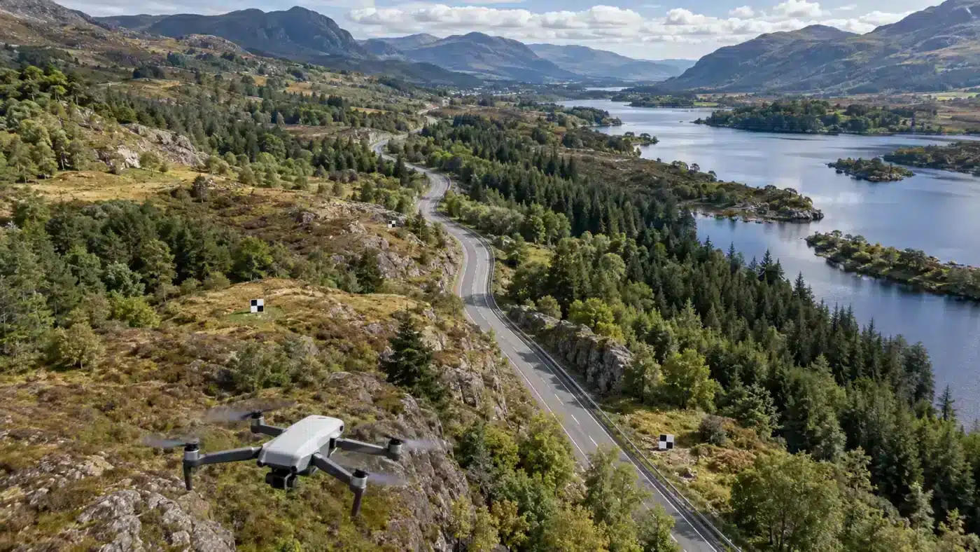
Roads, rivers, power corridors and pipelines invite a tempting flight plan: one long line of photographs down the asset. That design may cover the route visually yet provide a weak photogrammetric network. Corridor mapping with Agisoft Metashape works best when image geometry, ground reference and independent checks are designed for a long, narrow survey area from the outset.
Why a narrow strip is geometrically fragile
Adjacent images along one route share similar viewpoints. They may align, but the block has limited cross-corridor strength and can be sensitive to calibration errors or sparse reference points. A small systematic bias can accumulate along a long strip without creating an obviously dramatic image-matching failure. This is an engineering risk, not a universal prediction that every single-line flight will fail.
Agisoft recommends cross-route coverage for stronger aerial geometry in its aerial survey guidance. The ASPRS positional accuracy standards provide a broader framework for testing delivered geospatial data; a processing report alone is not a project accuracy specification.
Plan width as well as length
- Prefer multiple parallel lines over a single centerline when the site and flight permissions allow it. Include stable terrain or structures on both sides of the asset.
- Add selected crossing or oblique views near transitions, bridges, bends and other difficult geometry. They should share recognizable features with the main coverage.
- Follow terrain variation. A fixed absolute altitude over changing ground changes image scale, footprint and overlap. Review the actual camera-to-ground distance along the route.
- Limit scene changes. Wind in vegetation, moving traffic, changing water and shadows make repeated features harder to match.
- Place surveyed reference across the route and along its full length. Reserve independently measured check points near the ends, interior sections and critical crossings.
There is no single overlap percentage that guarantees success for every focal length, relief or surface. Use the camera footprint and required product resolution to design the mission, then inspect a representative test segment. Our overlap guide covers the image-footprint calculation; the GSD guide addresses resolution planning.
Process and verify by station
- Import photographs and confirm that camera coordinates and coordinate reference system are interpreted correctly.
- Align photos and inspect the entire route in plan and elevation. Look for disconnected sections, implausible camera positions and a sudden change in tie-point density.
- Use appropriately weighted control, optimize and inspect camera calibration. Do not hide an obviously deformed block by forcing every available surveyed point into the adjustment.
- Review independent check-point residuals by corridor segment. Report the ends and problematic transitions separately, rather than relying only on one project-wide average.
- Inspect the surface and orthomosaic at bridges, vegetation boundaries and steep slopes. A good plan-view seam does not prove good elevation accuracy.
For a linear asset, a simple station table can make the result auditable:
| Station/segment | Coverage check | Independent evidence |
|---|---|---|
| Start | Parallel and crossing views present? | Check-point XY and Z residuals |
| Middle | Consistent scale and tie-point connection? | Check-point residuals and surface inspection |
| End | Enough images beyond the delivery boundary? | Check-point residuals and edge inspection |
When to expand the survey footprint
If the asset is bordered by water, featureless fields or repeating structures, a wider capture footprint may be more valuable than simply adding more frames on the same line. If constraints prevent that, state the limitation and validate the delivered strip more densely. See our processing report guide for interpretation of residuals and coverage.
Control placement is a design problem
Imagine a long road survey with accurate reference clustered around the takeoff site. That cluster may anchor the start while leaving the far end weakly tested. A better plan distributes surveyed points over the full route and across its width wherever practical. Keep some points independent of the bundle adjustment. For a bridge or steep embankment, add validation at the elevations and surfaces that matter to the specification rather than judging only nearby flat pavement.
RTK imagery can reduce dependence on dense ground control, but the camera coordinates still require an appropriate datum, uncertainty settings and verification. If a project’s vertical error increases progressively along the line, check camera calibration, datum handling and control geometry before trying to fix the DEM with an arbitrary vertical shift.
Set acceptance criteria before flight
Define the deliverable footprint, horizontal and vertical accuracy method, minimum complete coverage, accepted voids and how vegetated or water-covered sections will be reported. For instance, an orthomosaic of road markings and an elevation model of roadside banks do not have identical data needs. Validate each product on suitable ground. The control and check-point article provides the distinction between constraining and testing the result.
During processing, inspect image footprints beyond both corridor ends; edge products are often least supported where the last image is also the delivery boundary. When a long route must be captured on several days, keep an overlap section between acquisitions and document changes in light, vegetation and camera configuration.
Different corridors fail in different ways
A highway may offer stable painted markings but introduce moving vehicles and vertical walls under bridges. A river offers little image texture over water and changes with flow, so the adjoining banks may be the reliable connection. A powerline route can have featureless fields and slender wires that are poorly resolved even when the terrain aligns. Plan the flight footprint around features that stay fixed between photographs and around the specific assets that must be delivered.
If a corridor crosses a ridge or deep valley, a nominal altitude above takeoff does not describe the image scale everywhere. Recalculate the nearest and farthest camera-to-surface distances, then check projected GSD and overlap at both extremes. A route that is adequate on level ground may contain a short, critical gap at a steep crossing.
Frequently asked questions
Can RTK camera positions replace cross-flight geometry?
RTK positions can constrain the block, but they do not create new viewing directions or solve weak image texture. Verify the result against independent points.
Do I need a GCP at every photograph?
No. Design a sensible distributed control network and separate check points. The number and spacing should follow the corridor length, terrain, expected accuracy and survey specification.
Technical basis: Agisoft aerial survey guidance and ASPRS positional accuracy standards.