

 Italiano
 Français
 Deutsch
 Español
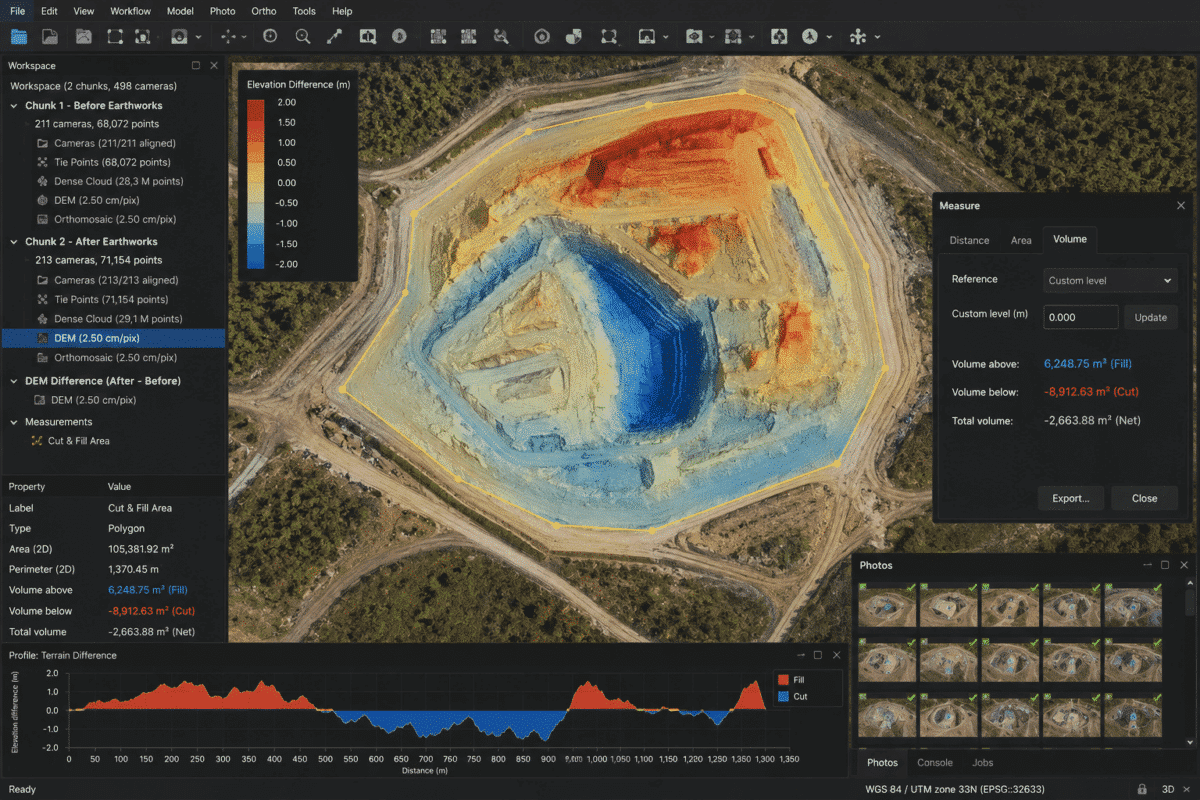
Calculating cut and fill volumes in Agisoft Metashape is a powerful workflow for construction, earthworks, road projects, mining, quarrying and site development.
By surveying a site with a drone before and after earthmoving operations, Metashape Professional can generate accurate Digital Elevation Models (DEMs) that allow you to identify where material has been excavated, where material has been added and how much the terrain has changed.
This makes drone photogrammetry particularly useful for monitoring excavation progress, grading operations, embankments and large construction sites where traditional ground measurements can be time-consuming.
In this guide, we explain how to calculate cut and fill volumes in Agisoft Metashape Professional, including two different workflows: measuring a surface relative to a reference plane and comparing two DEMs captured at different stages of a project.
What Are Cut and Fill Volumes?
In construction and earthworks, cut refers to material that must be excavated or has already been removed from the terrain.
Fill refers to material that must be added or has already been placed to raise the terrain to a required elevation.
Cut and fill calculations are commonly used for:
- Construction site preparation
- Road and railway projects
- Excavation monitoring
- Building foundations
- Embankments
- Quarry operations
- Mining projects
- Land grading
- Retention basins
- Large-scale earthmoving
Knowing these volumes helps project managers estimate material movement, monitor subcontractor progress and compare actual site conditions with previous surveys or design requirements.
Can Agisoft Metashape Calculate Cut and Fill?
Yes. Agisoft Metashape Professional provides several tools that can be used for cut and fill analysis.
There are two particularly useful approaches:
- Volume relative to a reference plane – useful when comparing terrain with a known level or simple base surface.
- DEM-to-DEM difference calculation – useful when comparing the same construction site at two different dates.
The second method is generally the more powerful approach for monitoring real earthworks progress because it compares two measured surfaces rather than assuming that the reference surface is flat.
Workflow 1: Cut and Fill Relative to a Reference Plane
For relatively simple areas, Metashape can calculate volume above and below a selected reference plane.
The general workflow is:
- Create the DEM.
- Open it in Ortho view.
- Draw a polygon around the area of interest.
- Right-click the polygon.
- Select Measure….
- Open the Volume tab.
- Select Best Fit, Mean Level or Custom Level.
Metashape reports:
- Volume Above
- Volume Below
- Total Volume
If the selected plane represents your target construction elevation, material above the plane can be interpreted as potential cut, while areas below the plane may represent required fill.
Best Fit, Mean Level or Custom Level?
Best Fit
The Best Fit plane is calculated from the elevations of the polygon boundary vertices and can accommodate a generally sloping surface.
This is useful when the perimeter of the area provides a reasonable approximation of the original terrain.
Mean Level
Mean Level creates a horizontal plane using the average elevation of the polygon vertices.
This is most appropriate where the reference surface is essentially level.
Custom Level
Custom Level allows you to specify an exact elevation manually.
This can be useful when the construction design calls for a known finished elevation, such as:
- A building pad
- A concrete slab
- A level platform
- A known excavation depth
- A storage yard
For complex construction sites, however, a single plane may not represent the real terrain accurately. This is where DEM difference analysis becomes particularly useful.
Workflow 2: Calculate Cut and Fill Between Two Drone Surveys
A more advanced workflow is to compare two DEMs representing the same site at different dates.
For example:
- DEM 1: site before excavation
- DEM 2: site after excavation and grading
Metashape Professional can subtract one DEM from another and create a new elevation layer showing the difference between the two surfaces.
This makes it possible to visualize exactly where terrain has increased or decreased.
Step 1: Perform the First Drone Survey
Capture the construction site before earthmoving begins.
Use consistent flight planning and good photogrammetric practices, including sufficient image overlap and appropriate Ground Sampling Distance.
For professional earthworks measurement, consider using:
- RTK drone coordinates
- PPK positioning
- Ground Control Points
- Independent checkpoints
Process the imagery in Metashape and create a georeferenced DEM representing the initial terrain.
Step 2: Perform the Second Drone Survey
After excavation, filling or grading operations have taken place, fly the site again.
For reliable comparison, try to maintain:
- The same coordinate reference system
- Similar flight altitude
- Similar Ground Sampling Distance
- Consistent RTK or GCP workflow
- Similar image overlap
- The same vertical datum
Process the second dataset and generate another DEM.
Step 3: Make Sure Both DEMs Use the Same Reference System
This step is critical.
If the DEMs use different horizontal coordinate systems, vertical datums or geoid definitions, the calculated difference may represent a coordinate-system mismatch rather than actual earth movement.
Before calculating cut and fill, verify that both surfaces are correctly aligned in:
- X position
- Y position
- Z elevation
- Coordinate reference system
- Vertical datum
Independent checkpoints can be particularly valuable because even a small systematic elevation offset between surveys can create a large apparent volume error across a large construction site.
Step 4: Load Both DEMs into the Same Metashape Project
If the DEMs were created in different chunks or external projects, one of them can be imported using:
File > Import > Import DEM…
Metashape supports importing DEM data in GeoTIFF raster format.
More than one DEM can be stored inside the same chunk, which allows the surfaces to be compared directly.
Step 5: Calculate the DEM Difference
Select the DEM that should be used as the primary surface and make sure it is set as the default DEM.
Then select:
Tools > Transform DEM…
Enable:
Calculation difference
and select the second DEM from the drop-down list.
Metashape will subtract the selected comparison DEM from the active DEM and create a new transformed DEM showing the elevation difference.
DEM Subtraction Order Is Important
The order of subtraction determines the meaning of positive and negative values.
For example, if you calculate:
Current Surface − Previous Surface
then:
- Positive elevation change indicates that material has been added: Fill.
- Negative elevation change indicates that material has been removed: Cut.
- Values near zero indicate little or no terrain change.
If you reverse the subtraction order, the signs will also be reversed.
For this reason, always document which DEM was subtracted from which before interpreting the results.
Step 6: Visualize the Earthworks Changes
The resulting difference DEM provides an intuitive representation of site changes.
Areas with positive values indicate terrain that is higher than in the previous survey, while negative areas indicate terrain that is lower.
This makes it much easier to identify:
- Excavated areas
- Filled areas
- Embankments
- New material stockpiles
- Grading progress
- Unexpected site changes
The difference surface can be particularly useful for construction progress reporting because it turns two complex elevation models into a direct map of terrain change.
Step 7: Calculate Cut and Fill Volumes from the Difference DEM
A practical way to quantify the difference surface is to measure it relative to a Custom Level of 0.
Open the difference DEM in Ortho view and draw a polygon around the construction area you want to analyze.
Then:
- Right-click the polygon.
- Select Measure….
- Open the Volume tab.
- Select Custom Level.
- Enter 0 as the reference level.
- Click Update.
If your difference DEM was calculated as:
Current DEM − Previous DEM
then the resulting volume values can be interpreted as:
- Volume Above 0 = Fill
- Volume Below 0 = Cut
Metashape also provides the Total Volume, which represents the net balance between the positive and negative volumes.
Cut Volume vs Fill Volume vs Net Volume
These values should not be confused.
Imagine that a project contains:
- 5,000 m³ of cut
- 3,500 m³ of fill
The site has experienced 8,500 m³ of total material movement, but the net change is only:
3,500 − 5,000 = −1,500 m³
A net value alone therefore does not describe the complete earthworks activity.
For construction reporting, it is usually better to present cut and fill separately in addition to the net balance.
Why Accurate Georeferencing Is Critical
Cut and fill volume errors can grow quickly across a large site.
Consider a 20,000 m² construction area with a systematic vertical error of only 5 cm.
The potential volume difference associated with that offset is approximately:
20,000 m² × 0.05 m = 1,000 m³
This demonstrates why centimeter-level vertical consistency between surveys is extremely important.
RTK positioning can help, but independent checkpoints are still recommended when volume measurements have contractual or financial consequences.
Common Cut and Fill Errors
Different Vertical Datums
If one DEM uses ellipsoidal heights and another uses orthometric heights, the entire difference map can be vertically shifted.
Inconsistent GCP Coordinates
Using different control networks between surveys can introduce systematic offsets.
Poor Polygon Boundaries
If the measurement polygon includes areas outside the actual earthworks zone, unrelated terrain changes may be included in the calculation.
Vegetation or Vehicles
Moving equipment, stockpiles, temporary structures and vegetation can appear as apparent elevation changes even though they are not part of the intended cut/fill calculation.
Using Only Net Volume
Net volume can hide substantial excavation and filling that cancel each other mathematically.
Always inspect Volume Above and Volume Below separately.
Cut and Fill for Construction Progress Monitoring
One of the biggest advantages of drone photogrammetry is that the survey can be repeated regularly.
For example, a contractor may fly the construction site:
- Before earthworks begin
- Every week during excavation
- After major grading stages
- Before progress payments
- At project completion
Each new DEM can be compared with the original surface or with the previous survey to quantify progress.
This creates an objective record of how much material has been removed or added over time.
Best Practices for Reliable Earthworks Measurements
- Use the same coordinate system for every survey.
- Use the same vertical datum and geoid.
- Maintain similar drone flight parameters.
- Use RTK, PPK or well-distributed Ground Control Points.
- Validate surveys using independent checkpoints.
- Remove or account for temporary objects where appropriate.
- Document the order of DEM subtraction.
- Use the same analysis boundaries for recurring measurements.
- Report cut, fill and net volume separately.
Final Recommendations
For simple construction areas, Agisoft Metashape cut and fill volume calculations can be performed relative to a Best Fit, Mean Level or Custom reference plane.
For professional earthworks monitoring, however, comparing two georeferenced DEMs is often more informative because it measures real surface change between two survey dates.
A recommended workflow is:
- Survey the site before earthworks.
- Generate the initial DEM.
- Survey the site again after earthmoving.
- Generate the current DEM.
- Verify that both surfaces use identical coordinate and vertical reference systems.
- Use Tools > Transform DEM > Calculation difference.
- Calculate Current DEM minus Previous DEM.
- Draw a polygon around the earthworks area.
- Measure the difference DEM using Custom Level 0.
- Interpret positive volume as fill and negative volume as cut.
With consistent survey procedures and accurate georeferencing, Agisoft Metashape Professional provides a powerful workflow for monitoring excavation, grading and material movement throughout the construction lifecycle.
Frequently Asked Questions
Can Agisoft Metashape calculate cut and fill volumes?
Yes. Metashape Professional provides DEM-based volume measurement tools and can also calculate differences between DEMs captured at different times.
How do I compare two DEMs in Metashape?
Load both DEMs into the same chunk, select the primary DEM and use Tools > Transform DEM. Enable Calculation difference and select the second DEM.
What does a positive DEM difference mean?
If the difference is calculated as Current DEM minus Previous DEM, a positive value means the current surface is higher and normally represents fill or added material.
What does a negative DEM difference mean?
If Current DEM minus Previous DEM is used, a negative value indicates that the surface has become lower and normally represents cut or excavated material.
Can I calculate cut and fill against a design elevation?
For simple horizontal design elevations, a Custom Level plane can be used. For complex design surfaces, a comparison between compatible elevation models generally provides a more representative workflow.
Why are my cut and fill volumes inaccurate?
Common causes include vertical offsets between surveys, different coordinate systems or vertical datums, weak georeferencing, temporary objects, vegetation and incorrect analysis boundaries.
Do I need RTK to calculate cut and fill volumes?
RTK is not mandatory, but accurate and consistent georeferencing is essential. Ground Control Points can also be used. Independent checkpoints are recommended when measurements need to be validated.
Should I report net volume or separate cut and fill?
For earthworks reporting, cut and fill should normally be reported separately. Net volume alone can hide large quantities of excavation and filling that offset each other mathematically.