

 Italiano
 Français
 Deutsch
 Español
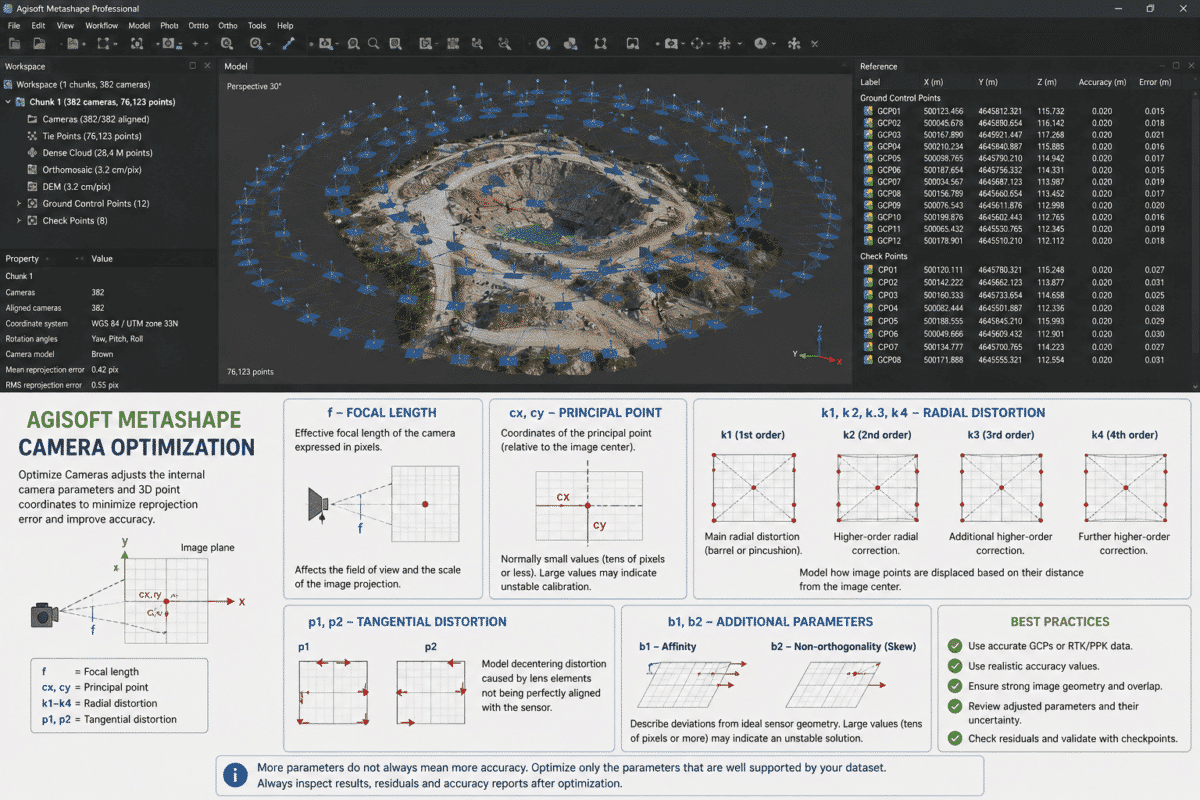
Agisoft Metashape camera optimization is one of the most important steps for improving the accuracy of a photogrammetric project, especially when processing drone surveys with Ground Control Points (GCPs), RTK or PPK camera coordinates.
When you open the Optimize Cameras dialog in Metashape, you will see parameters such as f, cx, cy, k1, k2, k3, k4, p1 and p2. For many users, the difficult question is not how to run optimization, but understanding what these parameters actually mean and which ones should be selected.
These values describe the internal geometry of the camera and the optical distortion introduced by the lens. If they are estimated incorrectly, the project can suffer from systematic deformation, poor vertical accuracy, excessive reprojection error or inconsistent results at Ground Control Points and checkpoints.
This guide explains each Metashape camera calibration parameter, how Optimize Cameras works and when different parameters should or should not be optimized.
What Does Optimize Cameras Do in Agisoft Metashape?
During Align Photos, Metashape estimates both the external orientation of the cameras and their internal calibration parameters.
External orientation describes where each camera was located and how it was rotated when the photograph was captured.
Internal orientation describes the geometry of the camera itself, including focal length, principal point position and lens distortion.
When you later select:
Tools > Optimize Cameras
or use the Optimize button in the Reference pane, Metashape performs another bundle adjustment.
During this process, the software adjusts estimated camera parameters and 3D point coordinates while attempting to minimize reprojection error and, when reference information is available, coordinate misalignment error.
Why Camera Optimization Matters
A camera is not a perfect mathematical imaging system.
Even high-quality mapping cameras contain small differences between their theoretical geometry and the way light actually reaches the sensor.
These differences can include:
- Slight variation in effective focal length
- Optical axis not passing exactly through the image center
- Radial lens distortion
- Lens decentering
- Manufacturing tolerances
- Focus-related calibration changes
Metashape estimates these effects using camera calibration parameters.
Correct estimation becomes particularly important in aerial mapping because small systematic errors across hundreds or thousands of photographs can produce noticeable deformation in the final model.
f: Focal Length
f represents the camera focal length expressed in pixels.
It is one of the most important internal calibration parameters because it directly affects the relationship between image coordinates and viewing geometry.
Although a camera lens may be advertised as 24 mm, 35 mm or another physical focal length, Metashape’s calibrated f value is expressed in pixels rather than millimeters.
The effective focal length estimated during photogrammetric calibration may differ slightly from the nominal manufacturer value.
This is normal.
For most normal photogrammetric projects, f should be included during optimization unless you are working with highly reliable pre-calibration values that you intentionally want to keep fixed.
cx and cy: Principal Point Coordinates
cx and cy describe the position of the camera’s principal point relative to the center of the image.
The principal point is where the optical axis of the lens intersects the sensor plane.
In a theoretically perfect camera, this point would coincide exactly with the geometric center of the sensor.
Real cameras normally show a small offset.
- cx represents the horizontal offset.
- cy represents the vertical offset.
Both values are expressed in pixels.
Agisoft notes that cx and cy values are normally relatively small, often a few dozen pixels or less.
If adjusted values become several hundred or even thousands of pixels, this may indicate an unstable or incorrect calibration solution rather than a real physical camera characteristic.
Why Can cx and cy Become Unrealistically Large?
Poor camera network geometry can make some calibration parameters difficult to estimate independently.
This is particularly relevant in aerial surveys where every photograph has almost the same orientation.
For example, flying every mapping line with the camera in exactly the same orientation can increase correlation between camera calibration parameters and project geometry.
Agisoft specifically recommends reviewing adjusted cx and cy values when diagnosing calibration problems.
If they become unrealistically large, it may be appropriate to fix those parameters and realign the dataset with a more restricted camera model.
k1, k2, k3 and k4: Radial Distortion
The parameters k1, k2, k3 and k4 describe radial lens distortion.
Radial distortion causes image points to be displaced according to their distance from the optical center of the image.
The effect generally becomes stronger toward the edges and corners of the photograph.
Two familiar forms of radial distortion are:
- Barrel distortion – straight lines appear to curve outward.
- Pincushion distortion – straight lines appear to curve inward.
Metashape uses a mathematical camera model to estimate and correct this distortion during photogrammetric processing.
k1
k1 is the first radial distortion coefficient and generally represents the dominant component of radial distortion.
k2
k2 adds a higher-order correction and helps describe more complex radial distortion toward the outer image area.
k3
k3 provides an additional higher-order radial correction.
It may become more relevant for lenses with stronger or more complex distortion.
k4
k4 is another higher-order radial distortion coefficient.
It should not automatically be enabled simply because more parameters appear to offer a more precise calibration.
Adding unnecessary parameters can increase correlation between calibration values and make the camera model less stable when the image network does not provide enough information to estimate them reliably.
Agisoft therefore provides specific workflow recommendations for certain cameras. For example, in its current DJI RTK workflow, Agisoft recommends excluding k4 when optimizing DJI Matrice 4E datasets.
p1 and p2: Tangential Distortion
p1 and p2 are tangential distortion coefficients.
Tangential distortion occurs when lens elements are not perfectly centered or aligned relative to the sensor.
Instead of distortion being purely radial around the optical center, image points can be displaced asymmetrically.
The p1 and p2 parameters model these decentering effects.
For standard photogrammetric cameras, these values are normally much smaller than the dominant radial distortion effects but can still be important for accurate calibration.
What About b1 and b2?
Although they are not always the focus of standard drone workflows, Metashape also provides:
- b1 – affinity coefficient
- b2 – non-orthogonality or skew coefficient
These values are expressed in pixels and describe additional deviations from an ideal camera sensor geometry.
Agisoft recommends examining these values together with cx and cy when diagnosing suspicious calibration results.
Values of tens or more for b1 or b2 may indicate an unstable calibration solution.
Camera Calibration Parameters at a Glance
| Parameter | Meaning | Unit |
|---|---|---|
| f | Focal length | Pixels |
| cx | Principal point horizontal offset | Pixels |
| cy | Principal point vertical offset | Pixels |
| k1 | 1st radial distortion coefficient | Dimensionless |
| k2 | 2nd radial distortion coefficient | Dimensionless |
| k3 | 3rd radial distortion coefficient | Dimensionless |
| k4 | 4th radial distortion coefficient | Dimensionless |
| p1 | 1st tangential distortion coefficient | Dimensionless |
| p2 | 2nd tangential distortion coefficient | Dimensionless |
| b1 | Affinity coefficient | Pixels |
| b2 | Non-orthogonality / skew | Pixels |
Which Parameters Should You Select in Optimize Cameras?
There is no universal checkbox combination that should blindly be used for every camera and every photogrammetric project.
For typical aerial mapping workflows, Agisoft recommends optimizing a broad set of calibration parameters after GCPs have been placed or when accurate RTK camera coordinates are being used.
However, specific cameras or project configurations may require some parameters to remain fixed.
Agisoft’s current RTK drone recommendations indicate that, in most cases, the complete parameter set can be optimized, with specific exceptions such as b1 and b2 in projects with GCPs and k4 for DJI Matrice 4E datasets.
These exceptions demonstrate why selecting every available checkbox is not always the best approach.
Adaptive Camera Model Fitting
Metashape includes an option called:
Adaptive camera model fitting
When enabled, Metashape automatically determines which interior camera orientation parameters should be adjusted.
This can help avoid unnecessarily fitting parameters that are poorly supported by the image geometry.
For users without a specific camera calibration strategy, adaptive model fitting can therefore provide a safer starting point than manually enabling every possible coefficient.
What Is Fit Additional Corrections?
The Optimize Cameras dialog also includes:
Fit additional corrections
Metashape normally uses Brown’s distortion model to describe camera distortion.
Agisoft explains that additional corrections can be enabled when the standard model does not describe the camera distortion sufficiently well.
This option estimates additional correction coefficients during optimization.
Agisoft notes that it can sometimes improve results when processing RTK drone imagery.
However, it should not be treated as a mandatory option for every project.
When Should You Run Optimize Cameras?
For professional aerial mapping, optimization is commonly performed after:
- Initial photo alignment
- Importing or verifying RTK/PPK camera coordinates
- Adding and accurately placing GCPs
- Setting correct camera and marker accuracy values
- Reviewing reference information
A typical sequence is:
- Align Photos
- Check alignment
- Add or verify GCPs
- Configure reference accuracy
- Optimize Cameras
- Review checkpoint and reprojection errors
- Continue to point cloud, DEM and orthomosaic generation
Why GCP Accuracy Settings Matter During Optimization
Optimize Cameras does not consider camera calibration in isolation.
When reference coordinates are enabled, Metashape attempts to balance image reprojection errors with errors relative to known reference coordinates.
This means that incorrect accuracy values can change how strongly Metashape trusts camera coordinates or Ground Control Points.
For example, assigning unrealistic centimeter accuracy to coordinates that are actually accurate only to several meters can force the bundle adjustment toward incorrect reference data.
Always use realistic camera and marker accuracy values.
How to Check the Adjusted Camera Calibration
After optimization, open:
Tools > Camera Calibration
and select the:
Adjusted tab.
This shows the camera calibration values estimated by Metashape.
Pay particular attention to:
- f
- cx and cy
- b1 and b2
- Radial distortion coefficients
- Parameter uncertainty
- Correlation between parameters
Use the Distortion Plot
Metashape also provides a Distortion Plot for evaluating the camera model.
This visualization can display:
- Total distortion
- Radial distortion
- Decentering distortion
- Additional corrections
- Residual reprojection errors
The residual plot is particularly useful because it can reveal systematic image-space patterns that suggest the selected camera model is not adequately describing the lens or camera system.
More Parameters Do Not Always Mean More Accuracy
This is one of the most important concepts in camera optimization.
It can be tempting to select every calibration parameter available in Metashape under the assumption that a more complex model must always be better.
That is not necessarily true.
Every additional parameter must be supported by enough independent information in the image network.
If the project geometry is weak, parameters may become strongly correlated with each other or with camera orientation and terrain shape.
The result can be an apparently low reprojection error but an unstable camera calibration and distorted model.
How to Improve Camera Calibration Stability
Good image acquisition helps Metashape separate camera distortion from project geometry.
Useful practices include:
- Use strong image overlap.
- Capture images from varied positions.
- Include oblique imagery when appropriate.
- Avoid highly repetitive flight geometry where possible.
- Use cross-flight lines for demanding survey projects.
- Rotate the camera orientation between flight lines where practical.
- Use accurate GCPs or RTK reference data.
- Use independent checkpoints to verify results.
A strong camera network is often more valuable than attempting to correct a weak dataset by enabling additional calibration coefficients afterward.
Should You Use Pre-Calibrated Camera Parameters?
Metashape allows known calibration parameters to be entered manually in:
Tools > Camera Calibration
If highly precise calibration information is available from a reliable laboratory calibration procedure, selected parameters can be fixed so they are not modified during Align Photos or Optimize Cameras.
However, nominal manufacturer specifications are not necessarily equivalent to a complete photogrammetric calibration.
For ordinary consumer and drone cameras, Metashape’s self-calibration during alignment and optimization is commonly used.
Common Camera Optimization Mistakes
Checking Every Parameter Without Understanding the Camera
More coefficients can create an unnecessarily complex and unstable camera model.
Ignoring Unrealistic cx and cy Values
Very large principal point offsets can indicate poor calibration rather than an unusual physical camera.
Optimizing Before GCP Placement
If GCPs will be used to constrain the final model, it is normally better to place and verify them before the final optimization.
Using Incorrect Reference Accuracy
Optimization depends on the relative weighting of image and reference measurements. Unrealistic accuracy values can produce misleading results.
Evaluating Only Reprojection Error
A low reprojection error does not automatically guarantee good absolute survey accuracy.
Independent checkpoints should also be examined whenever possible.
Final Recommendations
Agisoft Metashape camera optimization is not simply a button that should be run with every parameter selected.
Each calibration coefficient describes a specific physical or mathematical characteristic of the imaging system:
- f – focal length
- cx, cy – principal point position
- k1–k4 – radial lens distortion
- p1, p2 – tangential lens distortion
- b1, b2 – affinity and sensor non-orthogonality
For most professional drone mapping projects, optimize the camera after alignment and after reliable reference information has been added.
Use realistic accuracy settings, inspect the adjusted calibration values and validate the final result using checkpoints rather than relying exclusively on reprojection error.
Most importantly, remember that the ideal calibration model depends on the camera and image network. A simpler, well-constrained camera model can produce better survey results than a highly complex model whose parameters cannot be estimated reliably.
Frequently Asked Questions
What does f mean in Agisoft Metashape?
f is the calibrated focal length of the camera expressed in pixels.
What are cx and cy in Metashape?
cx and cy describe the horizontal and vertical position of the principal point relative to the image center, measured in pixels.
What are k1, k2, k3 and k4?
They are dimensionless radial distortion coefficients used to model lens distortion that changes with distance from the optical center of the image.
What are p1 and p2?
p1 and p2 are tangential distortion coefficients used to describe asymmetric lens decentering effects.
Should I optimize all camera parameters in Metashape?
Not automatically. The appropriate parameter set depends on the camera, dataset and survey geometry. Agisoft provides specific recommendations for some workflows and cameras.
When should I run Optimize Cameras?
For aerial mapping, optimization is commonly performed after photo alignment and after GCPs or accurate RTK/PPK reference information have been configured.
Should k4 be enabled for DJI Matrice 4E?
Agisoft’s current DJI RTK processing guidance recommends excluding k4 during camera optimization for DJI Matrice 4E projects.
What does Fit additional corrections do?
It allows Metashape to estimate additional corrections for distortions that are not adequately represented by its default Brown camera distortion model.