

 Italiano
 Français
 Deutsch
 Español
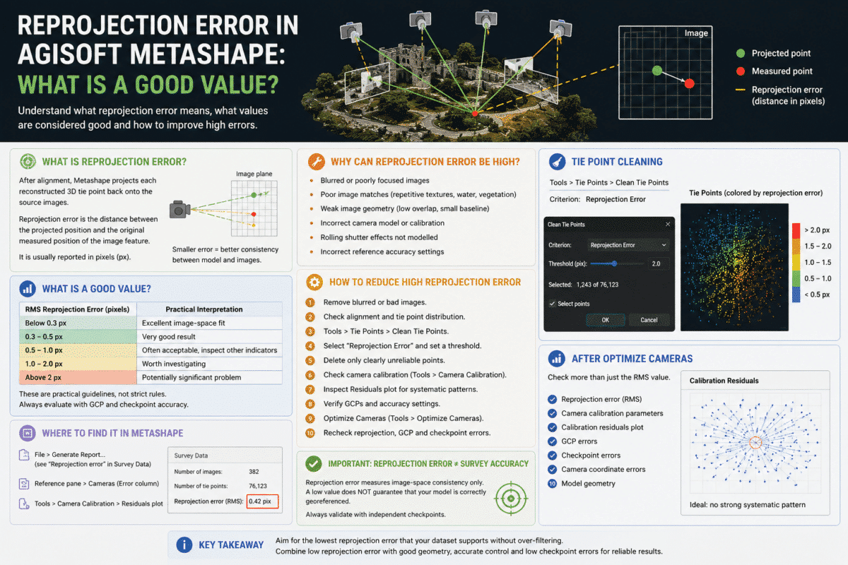
Reprojection error in Agisoft Metashape is one of the most commonly checked quality indicators after photo alignment, but it is also one of the most frequently misunderstood.
You may open a Metashape processing report and see a reprojection error of 0.35 pixels, 0.8 pixels or even several pixels. The obvious question is: what is a good reprojection error in Metashape?
There is no universal pass-or-fail number that applies to every camera, drone and photogrammetric project. However, reprojection error is extremely useful for identifying poor tie points, camera calibration problems, incorrect image matches and potentially unstable alignment.
As a practical rule of thumb, an RMS reprojection error below approximately 1 pixel is generally desirable, while values around 0.3–0.5 pixels are often considered very good for well-acquired aerial photogrammetry datasets. Values consistently above 1 pixel deserve closer inspection, while errors of several pixels can indicate a significant alignment or calibration problem.
These ranges should be treated as guidance rather than strict thresholds. A low reprojection error alone does not prove that a survey is accurate.
What Is Reprojection Error?
During photo alignment, Metashape identifies common image features across overlapping photographs and reconstructs their position in three-dimensional space.
Once a 3D tie point has been calculated, Metashape can mathematically project that point back onto each source photograph.
Reprojection error is the distance between where the reconstructed 3D point is predicted to appear in an image and where the corresponding feature was actually detected.
This difference is normally expressed in pixels.
For example, if Metashape predicts that a reconstructed point should appear at one position but the original detected image feature is 0.4 pixels away, the reprojection error associated with that observation is approximately 0.4 pixels.
Where Can You Find Reprojection Error in Metashape?
Metashape provides reprojection error information in several places.
One of the easiest is the processing report generated using:
File > Generate Report…
The Survey Data section includes the overall reprojection error for the project.
This value represents the root mean square reprojection error averaged over all valid tie points across all images.
You can also inspect camera and marker errors in the Reference pane and review image residuals through the Camera Calibration tools.
Why Does Metashape Show Reprojection Error in Pixels?
Reprojection error is fundamentally an image-space measurement.
It measures how well the calculated 3D geometry and camera calibration explain where features appear inside the original photographs.
This is why the value is expressed in pixels rather than directly in centimeters or meters.
A smaller pixel error generally means that the calculated camera geometry and reconstructed tie points agree more closely with the original image observations.
What Is a Good Reprojection Error in Agisoft Metashape?
There is no official single threshold that determines whether a Metashape project is good or bad.
However, the following ranges can be useful as a practical diagnostic guide for many conventional drone photogrammetry projects:
| RMS Reprojection Error | Practical Interpretation |
|---|---|
| Below 0.3 px | Excellent image-space fit in many datasets |
| 0.3–0.5 px | Very good result for many aerial projects |
| 0.5–1.0 px | Often acceptable, but inspect overall project quality |
| 1.0–2.0 px | Worth investigating for poor matches or calibration issues |
| Above 2 px | Potentially significant alignment or camera-model problem |
These values are not universal quality standards.
The correct interpretation depends on the camera, image sharpness, lens model, survey geometry, Ground Sampling Distance, number of tie points and the intended accuracy of the final deliverables.
Is 0.5 Pixel Reprojection Error Good?
For many well-acquired drone mapping datasets, an RMS reprojection error around 0.5 pixels or lower is a strong result.
It indicates that the reconstructed tie points and camera model explain the original image measurements with relatively small residuals.
However, a project with 0.4-pixel reprojection error can still have poor absolute georeferencing if the Ground Control Points, RTK coordinates or vertical datum are incorrect.
For survey applications, reprojection error should therefore always be evaluated together with GCP and independent checkpoint errors.
Is Reprojection Error the Same as Survey Accuracy?
No.
This is probably the most important concept to understand.
Reprojection error describes consistency inside image space. It does not directly tell you whether a point on the final orthomosaic or DEM is located at the correct real-world coordinate.
For example, a project can have:
- Excellent reprojection error
- Very consistent camera geometry
- A visually perfect orthomosaic
and still be shifted several meters because the input GPS coordinates or coordinate reference system are wrong.
Conversely, a project with slightly higher reprojection error may still provide excellent survey accuracy if the geometry, control network and checkpoints are reliable.
Reprojection Error vs GCP Error
These values measure different things.
Reprojection error measures the agreement between reconstructed 3D geometry and image observations.
GCP error measures the difference between the known reference coordinates of a Ground Control Point and its estimated position in the adjusted project.
For professional survey validation, checkpoints are even more important because they are not used to constrain the bundle adjustment.
A strong survey should therefore be evaluated using several indicators rather than optimizing exclusively for the lowest possible reprojection error.
Why Is My Reprojection Error High?
High reprojection error can have several causes.
Poor Image Matches
Incorrect tie point matches can cause reconstructed points to disagree strongly with their original image observations.
This can occur in areas containing repetitive textures such as:
- Roofs
- Crops
- Water
- Dense vegetation
- Similar building façades
Blurred Images
Motion blur, incorrect focus or poor exposure can reduce the precision with which image features are detected.
Poor Camera Calibration
If focal length, principal point or lens distortion parameters are not estimated correctly, systematic residual patterns may appear across the images.
Weak Image Geometry
Photographs captured from nearly identical positions or with insufficient baseline can produce unstable geometry.
Strong overlap and varied camera positions generally improve calibration and triangulation.
Rolling Shutter Effects
Cameras with electronic rolling shutters can introduce geometric deformation when the drone or camera moves during image capture.
If the camera uses a rolling shutter, the correct camera model should be configured where appropriate.
How to Find High Reprojection Error Tie Points
Metashape provides a tool for locating tie points with high reprojection error.
Switch to the Tie Points view and select:
Tools > Tie Points > Clean Tie Points
Select:
Reprojection Error
and adjust the threshold slider.
Metashape will select tie points that exceed the specified reprojection-error criterion.
High reprojection error often indicates poor localization accuracy or incorrect feature matches, so removing genuinely unreliable points can improve subsequent camera optimization.
Should You Delete All Tie Points Above 0.5 Pixels?
No.
This is a common mistake.
A threshold such as 0.5 pixels should not automatically be used as a universal deletion rule.
A large photogrammetric project contains many observations with different image scales, viewing angles and localization quality.
Aggressively deleting tie points simply to force the project toward an attractive reprojection-error number can weaken the image network and reduce geometric stability.
The objective is not to obtain the smallest possible number at all costs. The objective is to remove genuinely unreliable observations while maintaining a strong and well-distributed tie point network.
A Safer Tie Point Cleaning Workflow
A more controlled approach is:
- Align the photographs.
- Inspect the tie point cloud and camera alignment.
- Check the initial reprojection error.
- Use Tools > Tie Points > Clean Tie Points.
- Select the Reprojection Error criterion.
- Use a conservative threshold.
- Review how many points are selected.
- Delete only clearly unreliable points.
- Run Optimize Cameras.
- Recheck reprojection, GCP and checkpoint errors.
Avoid deleting a very large percentage of the tie point cloud in a single operation unless there is a clear reason to do so.
Why Optimize Cameras After Cleaning Tie Points?
Removing poor tie points changes the observations available to the photogrammetric bundle adjustment.
After editing the tie point cloud, run:
Tools > Optimize Cameras…
Optimize Cameras performs a full bundle adjustment, refining camera exterior orientation, internal calibration parameters and reconstructed tie point coordinates.
When reference data is present, Metashape considers image measurements together with camera coordinates, Ground Control Points, scale bars and their assigned accuracies.
This is why optimization should also be performed after changing GCP positions, camera coordinates or reference accuracy settings.
Use the Camera Calibration Residuals Plot
Looking only at one overall RMS number can hide systematic camera-calibration problems.
Open:
Tools > Camera Calibration
and inspect the Distortion Plot and Residuals.
The residuals graph represents averaged reprojection errors across different areas of the source images.
Ideally, the residual vectors should not show a strong systematic pattern.
If residuals consistently point in similar directions or become much larger near specific parts of the image, the default camera model may not fully describe the lens or the calibration may be unstable.
Why an Extremely Low Reprojection Error Can Be Misleading
A very small reprojection error may look impressive in a processing report, but it should never be treated as the only measure of project quality.
Over-parameterized camera calibration can sometimes fit image observations very closely while introducing parameter correlations or model deformation.
Similarly, aggressive tie point filtering can reduce the RMS reprojection error simply because many difficult observations have been deleted.
Always ask whether the project also has:
- Strong image geometry
- Well-distributed tie points
- Realistic camera calibration parameters
- Correct coordinate systems
- Accurate GCPs
- Low checkpoint errors
- No visible model deformation
Reprojection Error and Ground Sampling Distance
Reprojection error and Ground Sampling Distance are related conceptually but represent different spaces.
Reprojection error is measured in image pixels, while GSD describes the approximate ground dimension represented by one image pixel.
A lower GSD generally means finer ground detail, but you should not simply convert reprojection error into survey accuracy by multiplying the two values and treating the result as a guaranteed positional error.
Real-world accuracy also depends on camera geometry, triangulation, calibration, control points and many other factors.
How to Reduce High Reprojection Error
If your project shows unexpectedly high values, check the workflow systematically.
- Remove clearly blurred or damaged photographs.
- Verify camera alignment.
- Inspect tie points with high reprojection error.
- Remove obvious false matches conservatively.
- Check camera calibration parameters.
- Inspect the residuals plot.
- Confirm the correct rolling-shutter model where necessary.
- Use realistic reference accuracy settings.
- Verify GCP marker placement.
- Run Optimize Cameras after corrections.
What Should You Check After Optimization?
After running Optimize Cameras, do not look only at the new reprojection-error number.
Review:
- Overall RMS reprojection error
- Camera calibration parameters
- Camera calibration residuals
- GCP errors
- Checkpoint errors
- Camera coordinate errors
- Model geometry
For professional drone surveying, independent checkpoints remain one of the most useful indicators of whether the final model is accurately positioned in the real world.
Final Answer: What Is a Good Reprojection Error in Metashape?
For many conventional drone photogrammetry projects, an RMS reprojection error below approximately 1 pixel is a useful practical target.
Values around 0.3–0.5 pixels are often indicative of a very good image-space fit in a well-acquired aerial dataset.
However, there is no universal Metashape threshold that guarantees an accurate model.
If your reprojection error is above 1 pixel, inspect the tie points, camera calibration and image quality rather than immediately deleting large numbers of points.
If the value is already low, resist the temptation to aggressively filter the dataset simply to reduce it further.
The best Metashape project is not necessarily the one with the smallest reprojection error. It is the one that combines low image residuals, stable camera calibration, strong geometry and independently verified real-world accuracy.
Frequently Asked Questions
What is reprojection error in Agisoft Metashape?
Reprojection error is the distance between the observed position of an image feature and the position where the reconstructed 3D point is projected back onto the image.
Is 0.5 pixel reprojection error good?
For many aerial photogrammetry datasets, approximately 0.5 pixels or lower is a very good practical result, although it should not be treated as a universal accuracy threshold.
Is 1 pixel reprojection error acceptable?
A value around or below 1 pixel can be acceptable in many projects, but the complete project should also be evaluated using calibration residuals, GCP errors, checkpoints and model geometry.
Does low reprojection error mean high survey accuracy?
No. Reprojection error measures image-space consistency. Real-world accuracy must be evaluated using appropriate reference information, ideally including independent checkpoints.
How do I remove points with high reprojection error?
Use Tools > Tie Points > Clean Tie Points, select Reprojection Error and adjust the threshold. Remove unreliable points conservatively and optimize the cameras afterward.
Should I delete every tie point above 0.5 pixels?
No. A fixed threshold should not be applied blindly. Excessive filtering can weaken the tie point network and potentially reduce geometric stability.
Why did my reprojection error decrease after Optimize Cameras?
Optimize Cameras performs bundle adjustment and refines camera orientation, calibration and tie point coordinates using available image and reference measurements, which can improve the consistency of the reconstructed geometry.