Georeferencing is essential for producing accurate, real-world scaled 3D models and maps. Ground Control Points (GCPs) play a vital role in this process by anchoring your photogrammetry data to known Earth coordinates. In this guide, we’ll walk you through how to use GCPs in Agisoft Metashape to boost accuracy and reduce spatial error.
What Are GCPs and Why Are They Important?
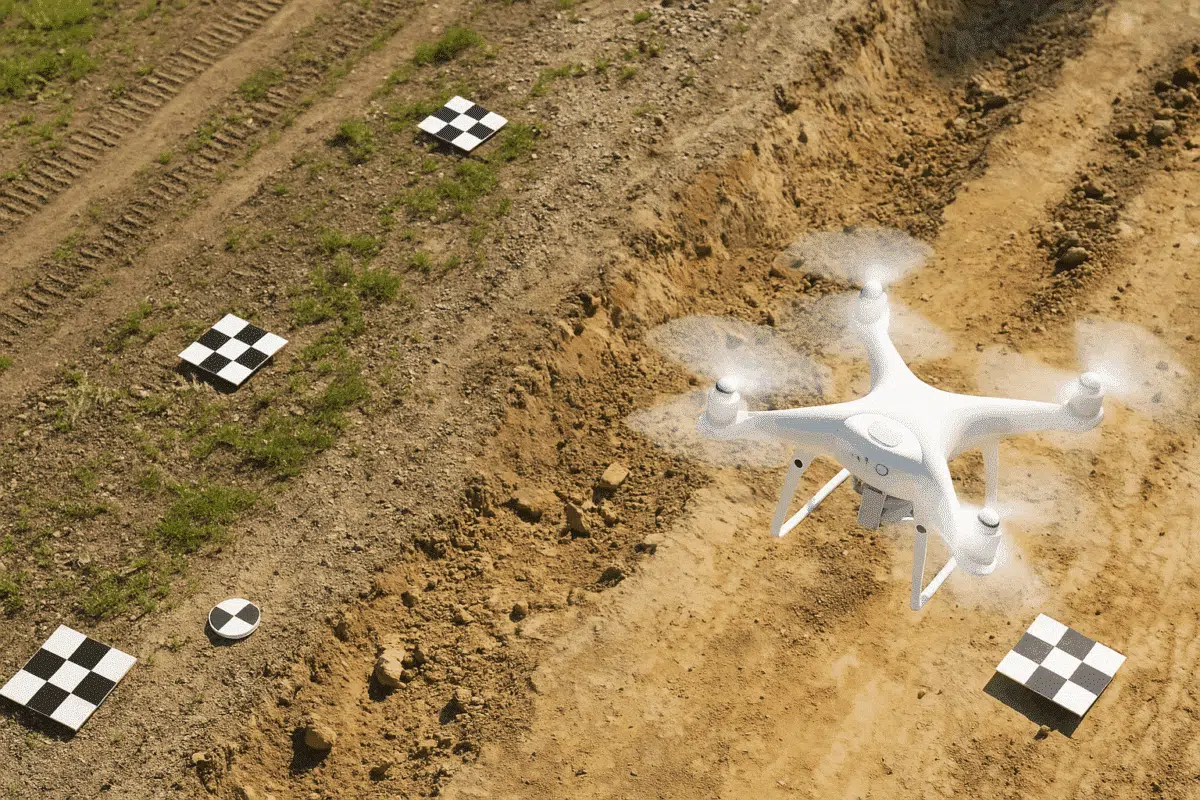
Ground Control Points are physical markers placed in the area you’re surveying, with known coordinates measured using GPS/RTK/PPK. When these points are identified in your drone photos, Metashape can use them to precisely position your 3D model in geographic space.
- Increased Accuracy: GCPs reduce the horizontal and vertical error in your model
- Better Alignment: Especially useful for aligning aerial images with other GIS data
- Survey-Grade Outputs: Essential for legal, engineering, or cadastral applications
Step 1: Prepare Your GCP Data
You’ll need a text or CSV file containing the GCP labels, coordinates, and optionally accuracy values. Format example:
GCP1, 432456.123, 5412345.678, 23.5
GCP2, 432460.001, 5412350.890, 23.8
Make sure the coordinate reference system (CRS) matches your drone imagery, such as UTM or WGS84 (EPSG code required).
Step 2: Import GCPs into Metashape
After aligning photos (via Workflow → Align Photos):
- Open the Reference pane (View → Reference)
- Click Import Markers or Import CSV
- Assign the correct CRS (e.g., EPSG:32633 for UTM Zone 33N)
- Markers will appear in the chunk and Reference pane
Step 3: Mark GCPs in Photos
This is the most time-consuming but essential step. Double-click each GCP in the Reference pane, and Metashape will open all photos where the point is visible.
- Zoom in and manually click the GCP in each image
- Use at least 3–5 photo marks per GCP for high accuracy
- Click “Estimate” to predict its position in other photos
The more precise your marking, the lower the final error will be.
Step 4: Optimize Camera Alignment
Once all GCPs are marked, select them in the Reference pane and right-click → Set Accuracy. For example, set horizontal/vertical accuracy to 0.03 m for RTK measurements.
- Uncheck any low-accuracy GCPs (use them as check points)
- Go to Tools → Optimize Cameras
- Select all parameters (f, cx, cy, k1, k2, p1, p2, etc.)
This step refines the internal camera calibration using GCPs and will reduce overall error.
Step 5: Check RMS Error
After optimization, review the RMS error values for each GCP in the Reference pane. Ideally:
- Under 2–3 cm RMS for high-accuracy work (RTK)
- Under 10 cm for consumer GPS-based workflows
You can also generate a report (File → Export → Export Report) to include GCP errors in PDF format.
Bonus: Use Check Points for Validation
To validate your model accuracy:
- Import extra GCPs and mark them
- Uncheck their “Enabled” checkbox
- They’ll be treated as check points instead of control
This lets you test how well your model aligns to real-world coordinates using independent data.
Best Practices for Using GCPs in Metashape
- Use well-distributed GCPs across the project area (at least 5–8)
- Avoid placing them all along the edges
- Use high-contrast targets (checkerboard, crosses)
- Collect GCPs with survey-grade GNSS when possible
Conclusion
Using GCPs in Agisoft Metashape is the key to achieving centimeter-level accuracy in your photogrammetric models. While marking and optimizing GCPs requires time and precision, the result is a georeferenced model ready for GIS, engineering, or legal applications. Follow the steps above, and your next survey project will meet the highest spatial accuracy standards.
Want to automate this workflow? Explore Metashape’s Python scripting API to import, mark, and optimize GCPs programmatically.