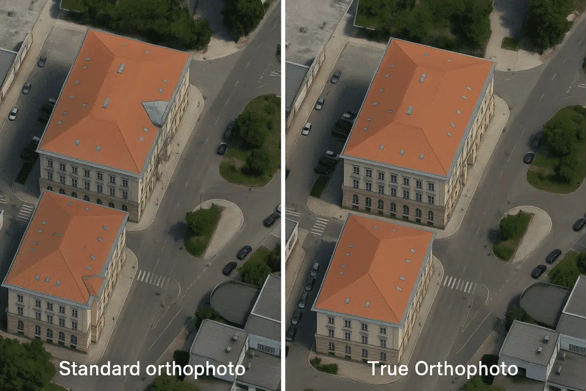
Agisoft Metashape is a powerful photogrammetry software used to generate high-resolution orthophotos, but standard orthophotos often suffer from one common issue in urban areas: building lean. This distortion occurs when tall structures appear tilted in the image due to off-nadir perspectives. In this guide, you’ll learn how to produce true orthophotos in Metashape by correcting for lean and achieving highly accurate, planimetric results.
What Is a True Orthophoto?
A true orthophoto is a geometrically corrected image where all elements—rooftops, ground features, and vertical structures—are placed in their exact overhead position. Unlike traditional orthophotos, which may retain distortions from camera angles, a true orthophoto removes these visual inconsistencies, especially in built environments.
This makes true orthophotos ideal for urban mapping, cadastral surveys, infrastructure planning, and any GIS application requiring precise object footprint placement.
Why Does Building Lean Happen?
Building lean occurs when photos are taken from an angle, causing tall structures to appear displaced from their actual base location. Even with nadir-oriented drones, minor tilts and terrain elevation can introduce lean effects, particularly when not corrected in post-processing.
Workflow to Create a True Orthophoto in Metashape
Step 1: Capture Sufficient Overlap with Oblique and Nadir Images
Use a drone with both nadir (vertical) and oblique (angled) camera angles. A cross-grid flight path with 80% front and 70% side overlap ensures the reconstruction of vertical surfaces like facades, which are necessary for lean correction.
Use a mechanical or software gimbal to maintain consistent tilt angles across shots.
Step 2: Align Photos and Build Dense Cloud
Import your images into Metashape and run “Align Photos” with high accuracy. Check the alignment quality, and remove any misaligned cameras. Then build the dense cloud at medium or high quality, ensuring enough detail for mesh generation.
Step 3: Generate a 3D Mesh Model
Rather than directly generating an orthophoto from the point cloud or DEM, create a 3D mesh model of the scene. This model includes vertical structures, not just ground elevation, allowing proper lean correction in the orthophoto.
Navigate to Workflow → Build Model, choose “Arbitrary (3D)” surface type and “Dense Cloud” as the source data.
Step 4: Set Up a Planar Projection Surface
To ensure accurate projection, create a planar projection surface. You can do this by generating a planar DEM or drawing a shape in the orthophoto view. This step defines the “camera” viewpoint for the orthorectification process.
Step 5: Build Orthomosaic from 3D Model
This is the most important step. Instead of generating the orthomosaic from a DEM (which ignores verticals), generate it from the mesh model. In Workflow → Build Orthomosaic, select:
- Surface: Model
- Blending mode: Mosaic
- Enable Hole Filling: Yes (optional)
- Enable Seamline Optimization: Yes
This approach includes vertical features in the ortho projection, correcting the apparent lean of buildings and objects.
Step 6: Export the True Orthophoto
Once the orthomosaic is generated, export it as GeoTIFF, JPEG, or PNG, depending on your application. Include projection (e.g., WGS84 UTM) and resolution settings (e.g., 5cm/pixel) for optimal GIS compatibility.
Tips for Better Accuracy
- Use GCPs (Ground Control Points) to improve geolocation accuracy.
- Fly in low-wind conditions to reduce image distortion and parallax errors.
- Calibrate your camera and use consistent exposure settings.
- Review seamlines in the orthomosaic editor to fine-tune blending areas.
Limitations of True Orthophotos
Even with lean correction, occlusions may still occur—areas hidden behind buildings or trees may remain untextured. In complex city environments, multiple flight heights and side-facing imagery can help address this.
Use Cases of True Orthophotos
- Cadastral mapping – shows real property boundaries without roof shift errors
- Urban planning – accurate building placement and infrastructure overlay
- Utility and telecom planning – correct pole, antenna, and rooftop equipment location
- Archaeological site documentation – clear top-down records without geometric warping
Conclusion
Creating true orthophotos in Agisoft Metashape is an advanced but highly rewarding technique. By projecting from the 3D model instead of a flat DEM, you can correct building lean and produce geometrically reliable imagery. This is essential for professionals in urban development, land administration, and any field where spatial precision matters. With the right capture and processing strategy, Metashape becomes a powerful tool for true orthophotography in 2025.